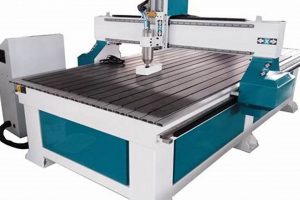
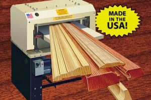
A desktop fabrication tool allows hobbyists and professionals to automate woodworking projects. Such a device integrates computer numerical control (CNC) technology with subtractive manufacturing, enabling the precise cutting, carving, and engraving of wood-based materials. An example is constructing intricate inlays for furniture or creating custom signage with detailed lettering.
The accessibility and affordability of these automated systems have revolutionized small-scale woodworking. Benefits include increased precision, repeatability, and the ability to execute complex designs beyond the scope of manual methods. Historically, these capabilities were confined to industrial settings, but advancements in electronics and open-source software have democratized access, allowing individuals to bring automated woodworking into homes and small workshops.
The following sections will delve into the core components, operational principles, software considerations, and practical applications of these user-assembled systems, offering a detailed exploration of their potential in various woodworking endeavors.
Essential Guidelines for Constructing Automated Woodworking Systems
Effective construction and utilization of automated woodworking setups require careful planning and execution. The following guidelines provide essential considerations for achieving optimal performance and project outcomes.
Tip 1: Structural Rigidity is Paramount: A robust frame is crucial for minimizing vibrations and ensuring accuracy. Utilize thick-walled aluminum extrusion or steel for the frame construction. Gussets and bracing should be incorporated at critical joints to further enhance rigidity.
Tip 2: Component Selection Based on Project Requirements: Choose stepper motors and lead screws appropriate for the size and type of projects intended. Larger projects necessitate higher torque motors and sturdier lead screw mechanisms.
Tip 3: Software Proficiency Enhances Capabilities: Familiarize yourself with computer-aided design (CAD) and computer-aided manufacturing (CAM) software. Mastering these tools unlocks the potential to create complex designs and generate optimized toolpaths.
Tip 4: Calibration and Testing are Essential: Thoroughly calibrate the axes of movement and conduct test cuts on scrap material. Precise calibration is vital for achieving accurate and repeatable results.
Tip 5: Dust Collection System Integration: Woodworking generates significant amounts of dust. Implement an effective dust collection system to maintain a clean workspace and protect the automated system’s components from particulate contamination.
Tip 6: Material Selection Influence The Outcome: The type of wood affect the cut depth. Soft wood requires smaller cut depth. Hard wood needs multiple passes.
Tip 7: Prioritizing Safety Protocol: Install emergency stop buttons. Be mindfull for the cables. Wear safety goggle to protect your eyes.
Adhering to these guidelines can significantly improve the performance, accuracy, and safety of a user-built automated woodworking system, leading to successful and satisfying woodworking endeavors.
The subsequent section will provide a comprehensive overview of common challenges encountered during construction and operation, along with effective troubleshooting strategies.
1. Precision Mechanics
In the context of user-assembled automated woodworking systems, precision mechanics refers to the quality and accuracy of the physical components responsible for movement and control. These components directly impact the accuracy, repeatability, and overall performance of the device. Their selection and proper implementation are critical for achieving desired woodworking results.
- Linear Motion Systems
Linear rails, bearings, and lead screws form the foundation of precise movement along the X, Y, and Z axes. The tolerances and smoothness of these components dictate the accuracy of cuts. For instance, using high-quality linear rails with minimal backlash ensures that the cutting tool follows the programmed path with minimal deviation. Inadequate components can lead to inaccuracies, such as jagged edges or dimensional errors in the finished product. The selection of ball screws over acme screws, for instance, can reduce friction and improve positioning accuracy.
- Drive Systems (Motors and Drivers)
Stepper or servo motors provide the power to drive the linear motion systems. The motor’s resolution (steps per revolution) and the driver’s micro-stepping capabilities influence the precision of movement. Higher resolution and micro-stepping allow for finer control and smoother motion, reducing the likelihood of vibrations or skipped steps. An appropriate driver must be selected to match the motors to provide adequate current and voltage for optimal performance. Inadequate motor torque can result in stalled movements, affecting the accuracy of the cut.
- Spindle and Tool Holding
The spindle, which holds the cutting tool, must be rigid and accurately aligned with the linear motion system. Runout (deviation from perfect rotation) in the spindle can significantly impact the quality of the cut. Using a high-precision collet system and ensuring proper tool clamping are essential. The spindle speed control is also essential in achieving the right cut depth and feed rate for any materials.
- Frame Rigidity and Vibration Damping
While not strictly a moving component, the frame supporting the entire system is integral to precision mechanics. A rigid frame minimizes vibrations, which can degrade the quality of the cut. Incorporating vibration-damping materials or techniques, such as using thicker frame members or adding mass, can further improve precision. The frame’s construction must prevent flexing or twisting during operation to maintain accurate alignment between all moving components.
These facets of precision mechanics are interconnected and collectively determine the overall capability of user-assembled automated woodworking machines. Optimizing each aspect, from component selection to careful assembly and calibration, is essential for achieving accurate and repeatable results in woodworking projects.
2. Software Integration
Software integration is a critical determinant in the functionality and usability of user-assembled automated woodworking systems. It bridges the gap between design intent and physical execution, enabling complex projects to be realized with precision. Effective software integration streamlines the workflow, optimizes machine performance, and expands the range of achievable designs.
- CAD/CAM Software Compatibility
Computer-Aided Design (CAD) software is used to create digital models of the desired woodworking projects. Computer-Aided Manufacturing (CAM) software then translates these designs into machine-readable instructions, or G-code, that dictate the movement of the cutting tool. Compatibility between these software packages and the machine’s control system is essential. For example, if the CAM software generates toolpaths incompatible with the machine’s controller, the project will fail. Furthermore, the ability to simulate the machining process within the software minimizes errors and material waste.
- Machine Control Software
The machine control software interprets the G-code and controls the movement of the motors, spindle speed, and other machine parameters. The interface should be user-friendly and provide real-time feedback on the machine’s status. Features such as manual jog controls, homing routines, and emergency stop functionality are crucial for safe and efficient operation. Examples include open-source options like LinuxCNC or commercial solutions tailored to specific controllers.
- Firmware and Driver Integration
The firmware embedded in the machine’s controller and the drivers installed on the host computer facilitate communication between the software and the hardware. Proper integration ensures that commands are accurately translated and executed. Issues such as driver conflicts or outdated firmware can lead to erratic machine behavior or complete system failure. Regular updates and compatibility checks are essential.
- Post-Processing Configuration
The post-processor is a software component that customizes the G-code output from the CAM software to match the specific requirements of the machine controller. Accurate post-processing ensures that the machine understands the toolpath commands correctly. For instance, different machines may require different G-code syntax or axis orientations. Failure to configure the post-processor correctly can result in incorrect toolpaths and damaged workpieces.
- Remote Monitoring
Being able to monitor jobs remotely is beneficial in the context of software integration because it allows a user to see the progress of the wood cutting. Not only that, error can be caught earlier.
The seamless integration of CAD/CAM software, machine control systems, firmware, and post-processing is paramount for realizing the full potential of user-assembled automated woodworking machines. Effective integration streamlines the workflow, enhances accuracy, and expands the possibilities for intricate and complex woodworking projects.
3. Material Compatibility
Material compatibility is a critical consideration in the effective utilization of user-assembled automated woodworking systems. The selection of appropriate materials, coupled with proper machining parameters, directly influences the quality of the finished product, the lifespan of cutting tools, and the overall operational efficiency of the equipment. Incompatibility can lead to poor cut quality, tool breakage, and even damage to the machine itself.
- Wood Hardness and Density
The hardness and density of wood species significantly affect the cutting parameters. Hardwoods, such as oak or maple, require slower feed rates and higher spindle speeds compared to softwoods like pine or cedar. Attempting to cut hardwoods with parameters optimized for softwoods can result in excessive tool wear, poor surface finish, or even stall the machine. Conversely, using excessively high feed rates on softwoods can lead to splintering and inaccurate cuts.
- Material Composition (Natural vs. Engineered)
Natural wood possesses variable grain patterns and inherent inconsistencies, requiring adaptive machining strategies. Engineered wood products, such as MDF or plywood, offer more uniform properties but introduce considerations related to adhesives and binders. Machining MDF, for instance, generates a fine dust that necessitates effective dust collection. Plywood may exhibit voids or inconsistencies in veneer layers, potentially impacting cut quality. The type of adhesive used in engineered wood can also affect tool wear and cutting parameters.
- Cutting Tool Selection and Geometry
The geometry and material of the cutting tool must be compatible with the wood being machined. Different bit types, such as straight flute, spiral flute, or compression bits, are suited for specific materials and applications. For example, compression bits are often used for plywood to minimize tear-out on both the top and bottom surfaces. The tool material, such as carbide or high-speed steel, influences its durability and ability to maintain a sharp cutting edge. Machining abrasive materials requires more durable tools to prevent premature wear.
- Workholding Methods and Material Support
The method of securing the workpiece to the machine bed must be appropriate for the material being machined. Inadequate workholding can lead to vibration, movement, or even ejection of the workpiece during cutting. Soft materials may require gentle clamping pressure to avoid damage, while harder materials necessitate more robust clamping to prevent slippage. Proper material support is also crucial to prevent sagging or flexing, particularly when machining large or thin workpieces.
These facets of material compatibility are intrinsically linked to the successful operation of user-assembled automated woodworking machines. Careful consideration of wood properties, material composition, tool selection, and workholding methods ensures optimal cutting performance, extended tool life, and high-quality finished products. Failure to address these factors can lead to suboptimal results and potentially damage the machine itself.
4. Safety Protocols
The construction and operation of user-assembled automated woodworking systems inherently involve potential hazards. Adherence to established safety protocols is paramount to mitigate risks and ensure the well-being of the operator and those in the surrounding environment. These protocols encompass a range of measures, from engineering controls to personal protective equipment and safe work practices.
- Emergency Stop Systems
Emergency stop (E-stop) systems are critical safety features that allow for immediate shutdown of the machine in the event of an anomaly or hazardous situation. Placement of readily accessible E-stop buttons is essential. For example, if a cutting tool breaks or the workpiece becomes dislodged, activating the E-stop can prevent further damage or injury. The E-stop system should cut power to all critical components, including motors and the spindle, bringing the machine to a complete halt. Regular testing of the E-stop functionality is vital to ensure its proper operation.
- Personal Protective Equipment (PPE)
Appropriate PPE is necessary to protect against hazards such as flying debris, noise, and dust. Safety glasses or face shields safeguard against projectiles generated during cutting operations. Hearing protection, such as earplugs or earmuffs, reduces exposure to potentially damaging noise levels. Respirators or dust masks filter airborne particulate matter, preventing inhalation of harmful wood dust. The selection of PPE should be based on a thorough risk assessment of the specific tasks being performed.
- Enclosure and Interlock Systems
Enclosing the automated woodworking system can contain dust, reduce noise, and prevent accidental contact with moving parts. Interlock systems ensure that the machine cannot operate if the enclosure doors or panels are open. For instance, if someone attempts to access the machine while it is running, the interlock system will automatically halt operation, preventing potential injury. The enclosure should be constructed of durable materials that can withstand impacts from flying debris.
- Dust Collection and Ventilation
Woodworking generates significant quantities of dust, which can pose respiratory health hazards and create fire risks. Effective dust collection systems, such as shop vacuums connected to the cutting tool, capture dust at the source. General ventilation improves air quality and reduces the concentration of airborne particulate matter. Regular cleaning of the work area prevents dust accumulation, further minimizing the risk of fire or respiratory irritation.
The integration of these safety protocols into the design, setup, and operation of user-assembled automated woodworking machines is not merely a recommendation, but a fundamental necessity. Consistent adherence to these measures significantly reduces the likelihood of accidents and promotes a safe working environment for all involved.
5. Rigidity Framework
The structural integrity of a user-assembled automated woodworking system is largely dictated by its rigidity framework. This framework serves as the foundation upon which all other components are mounted, and its stiffness directly influences the accuracy, precision, and stability of the machine during operation. A well-designed and constructed framework minimizes vibrations, reduces deflection under load, and ensures consistent performance.
- Material Selection and Properties
The choice of materials for the framework significantly impacts its overall rigidity. Steel, aluminum, and composite materials are commonly employed. Steel offers high stiffness and strength but is heavier and more susceptible to corrosion. Aluminum provides a good balance of stiffness and weight and is corrosion-resistant. Composite materials can offer exceptional stiffness-to-weight ratios but are more complex to work with. The material’s Young’s modulus, a measure of its stiffness, is a key factor in determining the framework’s resistance to bending and deflection. For example, a frame constructed from thick-walled steel tubing will exhibit significantly less deflection under load compared to a frame made from thin-walled aluminum.
- Structural Design and Geometry
The geometrical arrangement of the framework members plays a crucial role in its rigidity. Triangular or truss-like structures are inherently more rigid than simple rectangular frames. Gussets, bracing, and cross-members can be added to reinforce weak points and distribute loads more effectively. The placement and orientation of these structural elements are critical to minimizing stress concentrations and preventing deformation. For instance, a frame with well-placed cross-members will be more resistant to twisting and bending compared to a frame with only perimeter members.
- Joint Connections and Fasteners
The method of joining the framework members significantly influences its overall stiffness. Welded joints provide the highest degree of rigidity, but require specialized equipment and expertise. Bolted connections are more versatile and easier to assemble, but can introduce compliance due to fastener looseness or deformation. Using high-strength fasteners, lock washers, and proper tightening techniques is essential to maintain joint integrity. For example, a frame with poorly executed bolted connections will be prone to vibration and misalignment, negatively impacting the machine’s accuracy.
- Damping and Vibration Isolation
Even with a rigid framework, vibrations generated by the cutting process or machine components can still affect performance. Incorporating damping materials or vibration isolation mounts can help to minimize these effects. Damping materials absorb vibrational energy, while isolation mounts decouple the machine from its surroundings. For example, placing rubber pads between the machine and its support surface can reduce the transmission of vibrations to the surrounding environment.
The design and construction of a rigid framework are fundamental to the successful operation of a user-assembled automated woodworking system. Careful consideration of material selection, structural design, joint connections, and damping techniques is essential to ensure the machine’s accuracy, stability, and longevity. A robust framework not only enhances performance but also improves safety by reducing the risk of machine failure or instability.
6. Calibration Methods
The precise operation of any user-assembled automated woodworking system is contingent upon accurate calibration. Calibration methods address inherent mechanical inaccuracies, ensuring that programmed movements align with actual toolpath trajectories. Without proper calibration, the system’s potential for precise woodworking is severely compromised.
- Axis Calibration and Step Resolution
Axis calibration involves determining the relationship between commanded movement and actual displacement along each axis (X, Y, and Z). Step resolution, defined as the distance the tool moves per step of the stepper motor, must be accurately determined and configured in the machine’s control software. Incorrect step resolution leads to dimensional errors in the finished workpiece. For instance, if the X-axis is calibrated incorrectly, a square feature may be cut as a rectangle. Calibration is typically achieved by measuring the actual travel distance over a known commanded distance and adjusting the steps per millimeter setting in the control software accordingly.
- Backlash Compensation
Backlash, the play or looseness in mechanical components such as lead screws and gears, introduces inaccuracies in movement, particularly when changing direction. Backlash compensation techniques, implemented in the control software, account for this play by adding a small amount of movement to overcome the backlash. Failure to compensate for backlash results in dimensional errors and inconsistent cuts, especially when machining intricate details. Accurate measurement of backlash is crucial for effective compensation. This can be achieved through dial indicators or specialized calibration tools.
- Orthogonality Correction
Orthogonality refers to the squareness of the axes of movement. If the X and Y axes are not perfectly perpendicular, it introduces distortion in the machined parts. Orthogonality correction involves adjusting the machine’s geometry to ensure that the axes are square to each other. This may involve shimming or adjusting the alignment of linear rails. Specialized calibration squares or electronic levels can be used to measure and correct orthogonality errors. Misalignment of axes could lead to inaccurate joinery in woodworking projects.
- Tool Offset Calibration
Tool offset calibration determines the precise location of the cutting tool’s tip relative to the machine’s coordinate system. This is essential for accurate machining, especially when using multiple tools or performing tool changes. Incorrect tool offsets can lead to cuts that are too deep or too shallow, or to features that are misaligned. Tool offset calibration is typically performed using touch probes or manual measurement methods. Accurate tool offset calibration is vital for producing parts that meet precise dimensional requirements.
These calibration methods are indispensable for achieving optimal performance from user-assembled automated woodworking systems. Accurate calibration ensures that the machine operates within its specified tolerances, producing parts that meet design specifications. Regular calibration is recommended to maintain accuracy over time, as mechanical components can wear or shift. Proper calibration is a cornerstone of precision woodworking with these machines.
7. Toolpath Optimization
Toolpath optimization is a crucial element in maximizing the efficiency, accuracy, and surface finish quality achievable with user-assembled automated woodworking machines. Effective toolpath strategies minimize machining time, reduce tool wear, and enhance the overall precision of the finished product. The following aspects highlight the key considerations in optimizing toolpaths for these systems.
- Cutting Strategy Selection
The choice of cutting strategy, such as rastering, contouring, or pocketing, significantly impacts machining time and surface finish. Rastering, where the tool moves back and forth in parallel lines, is suitable for large areas but can leave visible tool marks. Contouring, which follows the outline of a shape, is often used for finishing passes. Pocketing strategies efficiently remove material from enclosed areas. The optimal strategy depends on the geometry of the workpiece and the desired surface finish. For example, adaptive clearing strategies can reduce stress on the machine while roughing, reducing the likelihood of errors and mechanical stress.
- Feed Rate and Spindle Speed Optimization
The feed rate (the speed at which the tool moves through the material) and spindle speed (the rotational speed of the cutting tool) must be carefully selected to match the material being machined and the tool being used. Excessive feed rates can lead to tool breakage, poor surface finish, or machine stalling. Insufficient feed rates can increase machining time and cause the tool to rub against the material, generating heat and reducing tool life. The optimal feed rate and spindle speed are often determined through experimentation or by consulting tooling manufacturers’ recommendations. For instance, hardwood requires slower feed rates and higher spindle speeds than softwood.
- Tool Engagement and Stepover Control
Tool engagement refers to the amount of the cutting tool that is in contact with the material at any given time. Excessive tool engagement can overload the machine and lead to vibrations or tool breakage. Stepover, the distance the tool moves laterally between passes, affects the surface finish and machining time. Smaller stepovers result in smoother surfaces but increase machining time. Controlling tool engagement and stepover is essential for achieving a balance between efficiency and quality. For example, trochoidal milling techniques can reduce tool engagement and allow for higher feed rates.
- Entry and Exit Strategies
The manner in which the cutting tool enters and exits the material significantly influences the surface finish and tool life. Plunging directly into the material can create stress concentrations and leave visible marks. Ramping or helical entry strategies provide a smoother transition and reduce the risk of tool breakage. Similarly, carefully planned exit strategies can minimize tear-out and prevent damage to the workpiece. For instance, a tangential lead-out move can prevent a sharp edge from forming at the end of a cut.
Optimizing toolpaths is an iterative process that requires experimentation and a thorough understanding of the capabilities of the user-assembled automated woodworking system. By carefully selecting cutting strategies, optimizing feed rates and spindle speeds, controlling tool engagement, and implementing appropriate entry and exit strategies, users can maximize the efficiency, accuracy, and surface finish quality of their woodworking projects. Efficient toolpaths minimizes waste of woods
Frequently Asked Questions
The following questions address common inquiries and misconceptions regarding the construction and operation of user-assembled automated woodworking machines. The answers provided offer concise and factual information to assist prospective users.
Question 1: What is the expected level of precision achievable with a user-assembled automated woodworking machine?
Precision is influenced by component quality, machine rigidity, and calibration accuracy. While industrial-grade precision is not generally attainable, accuracies of 0.1mm to 0.05mm are possible with careful construction and setup.
Question 2: How significant is the initial investment for such a system?
The initial investment varies widely depending on the size, capabilities, and component selection. A basic system can range from \$500 to \$2000, while more advanced systems with larger work areas and enhanced features can exceed \$5000.
Question 3: What level of technical expertise is required for assembly and operation?
Assembly requires a moderate level of mechanical and electrical knowledge. Operation necessitates familiarity with CAD/CAM software and basic G-code programming. Online resources and communities provide support for novice users.
Question 4: What are the typical maintenance requirements for these systems?
Maintenance includes regular cleaning, lubrication of moving parts, inspection of wiring and connections, and periodic calibration. Component replacement may be necessary over time due to wear and tear.
Question 5: What is the expected lifespan of a user-assembled automated woodworking machine?
Lifespan is dependent on usage frequency, maintenance practices, and component quality. With proper care, a well-constructed system can provide several years of reliable service.
Question 6: What safety precautions are essential when operating these machines?
Mandatory safety precautions include wearing appropriate personal protective equipment (PPE), using emergency stop systems, implementing dust collection, and adhering to safe operating procedures at all times.
The information provided in these FAQs offers a foundational understanding of user-assembled automated woodworking systems. Prospective users are encouraged to conduct thorough research and seek expert advice before embarking on such a project.
The following section will explore emerging trends and future developments in the field of automated woodworking.
Conclusion
This article has comprehensively explored the domain of user-assembled automated woodworking equipment. Core aspects were examined, encompassing mechanical precision, software integration, material suitability, safety regulations, structural solidity, calibration methodologies, and optimization of toolpaths. A thorough comprehension of each element is crucial for the effective construction and deployment of these systems.
The increasing accessibility of automated fabrication technology presents both opportunities and challenges. Continued innovation in materials, software, and control systems will undoubtedly expand the capabilities of such machines, while responsible implementation and adherence to safety standards remain paramount. Further development promises to democratize advanced manufacturing techniques, enabling increased creativity and efficiency within woodworking and related crafts.


