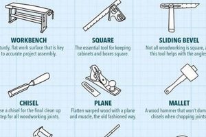
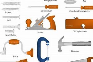
Creating woodworking schematics manually involves producing detailed diagrams and instructions for constructing projects using drafting tools and techniques. This process typically includes orthographic projections, dimensioning, and section views to accurately represent the design. For example, a plan for a simple table might include a top view showing the overall dimensions, a side view illustrating the leg and apron details, and a section view displaying joinery methods.
The skill of manual woodworking design offers benefits such as enhanced spatial reasoning, a deeper understanding of construction principles, and the ability to customize designs without reliance on technology. Historically, all woodworking projects relied on hand-drawn plans, fostering a rich tradition of craftsmanship and precise execution. Even today, this methodology allows for a tactile engagement with the design process and an intimate connection to the finished product.
The subsequent sections will delve into the necessary tools and materials, fundamental drafting techniques, and effective methods for dimensioning and annotating woodworking designs to provide a solid foundation for creating precise and practical construction blueprints.
Tips for Manual Woodworking Plan Creation
The following tips offer practical guidance for producing accurate and effective woodworking plans using manual drafting techniques. Each point addresses a specific challenge or area for improvement in the planning process.
Tip 1: Employ a consistent scale for all drawings to ensure dimensional accuracy and ease of interpretation. Choose a scale appropriate for the project’s size and complexity, such as 1:10 for smaller objects or 1:20 for larger furniture pieces.
Tip 2: Master orthographic projection to represent three-dimensional objects accurately on a two-dimensional surface. This involves creating top, front, and side views that align precisely, allowing for a complete understanding of the object’s form.
Tip 3: Utilize accurate dimensioning techniques, including extension lines, dimension lines, and arrowheads, to clearly indicate the size and location of all features. Dimensions should be placed outside the object whenever possible and should be easily readable.
Tip 4: Incorporate section views to reveal internal details and joinery methods. Clearly indicate the cutting plane with a section line and hatching to differentiate the cut surface from other elements.
Tip 5: Employ architectural lettering for annotations and labels, ensuring legibility and consistency throughout the plan. Use a consistent letter height and spacing for a professional and easily understandable appearance.
Tip 6: Use different line weights to distinguish between object lines, hidden lines, and center lines. Thicker lines should represent visible edges, while thinner lines should indicate hidden features or reference points.
Tip 7: Proofread the plan meticulously for dimensional errors, omissions, and inconsistencies. Have another individual review the plan to identify potential mistakes.
Implementing these suggestions can significantly improve the clarity and accuracy of woodworking plans, leading to more successful and efficient project execution. These techniques ensure a shared understanding between the designer and the craftsman, mitigating potential errors and misunderstandings.
The next section will provide an overview of advanced techniques in this manual drafting.
1. Scale and Proportion
Scale and proportion are fundamental aspects of how woodworking plans are manually drafted. The selected scale determines the size at which the project is represented on paper, directly impacting the accuracy and readability of the drawing. Incorrect scaling can lead to misinterpretations of dimensions and ultimately result in construction errors. For instance, if a plan is drawn at a scale that is too small, intricate details, such as dovetail joints or small moldings, may be difficult to represent accurately. Conversely, a scale that is too large can make the overall plan unwieldy and impractical to manage.
Proportion, closely linked to scale, involves maintaining the correct relationships between different parts of the project within the drawing. If the proportions are skewed, even with accurate scaling, the final product will not match the intended design. Consider a plan for a chair: if the legs are drawn disproportionately long or short relative to the seat, the chair’s aesthetic appeal and structural integrity would be compromised. Maintaining correct proportions requires a keen eye for detail and a thorough understanding of the project’s overall design.
Therefore, when creating woodworking schematics manually, it’s essential to carefully consider the scale and ensure the proportions are accurate. Consistent use of appropriate drafting tools, such as scaled rulers and proportional dividers, aids in achieving accuracy. The importance of accurate scale and proportion cannot be overstated, as they are crucial for successful project execution. Failure to address these elements can lead to wasted materials, time, and ultimately, unsatisfactory results.
2. Orthographic Projection
Orthographic projection forms a cornerstone of manual woodworking plan creation. This technique involves depicting a three-dimensional object using two-dimensional views, typically top, front, and side. The accurate representation of these views, aligned precisely, allows for a complete and unambiguous understanding of the object’s shape and dimensions. Without proper orthographic projection, critical details such as joinery placement, component thickness, and overall proportions can be misinterpreted, leading to errors during the construction phase. As an illustration, consider a plan for a cabinet: orthographic projection is vital to accurately display the placement of shelves, the dimensions of the doors, and the method of attaching the back panel. Each view provides specific information that, when combined, yields a comprehensive understanding of the cabinet’s design.
The application of orthographic projection in manual woodworking planning extends beyond simply creating visual representations. It serves as a tool for identifying potential design flaws or construction challenges before any material is cut. By carefully examining the various views, interferences or inconsistencies can be detected, allowing for corrections and adjustments to be made during the planning stage. For instance, orthographic projection can reveal whether two components will collide when assembled or if a particular joint design is structurally unsound. This proactive approach minimizes waste and reduces the likelihood of costly mistakes during the construction process. A practical application involves designing a complex joint, such as a mortise and tenon; accurate orthographic views allow for precise measurements and ensure proper fit.
In conclusion, orthographic projection is not merely an optional element but an essential technique within the realm of manual woodworking schematics. Its accurate application enables a complete understanding of the design, facilitates the identification of potential problems, and ultimately contributes to a successful project outcome. While modern CAD software automates this process, the fundamental principles of orthographic projection remain crucial for effective woodworking planning, particularly when relying on manual drafting techniques. Challenges inherent in manual drafting underscore the need for meticulous attention to detail and a thorough grasp of these principles.
3. Dimensioning Standards
Dimensioning standards are integral to the process of manually creating woodworking designs. These standards dictate the rules and conventions for indicating measurements on a drawing, ensuring clarity, accuracy, and consistency. A design, no matter how visually appealing, is rendered impractical without clear and precise dimensioning. The relationship between proper dimensioning and a usable plan is causal: adhering to standards directly results in a plan that can be accurately interpreted and followed by a woodworker. For example, consistent placement of dimension lines, extension lines, and arrowheads prevents ambiguity, allowing the craftsman to confidently cut and assemble the components. Without such standardization, misinterpretations are inevitable, leading to errors and wasted materials.
Specifically, dimensioning standards address aspects such as the placement of dimensions relative to the object, the use of leaders for notes, the indication of tolerances, and the representation of holes and curves. For instance, a standard dictates that dimensions should be placed outside the object whenever possible to avoid cluttering the drawing. Similarly, a standard specifies the format for indicating the diameter of a hole or the radius of a curve. The practical application of these standards is evident in any woodworking project. Consider a plan for a table: the dimensions must clearly indicate the length, width, and thickness of each component, as well as the location of any joints or hardware. Adherence to dimensioning standards ensures that all of these measurements are easily understood and can be accurately reproduced in the physical world.
In summary, dimensioning standards are not merely guidelines but essential components of any manual woodworking blueprint. They provide a framework for communicating precise measurements, reducing the potential for errors and ensuring that the final product conforms to the intended design. While digital tools offer automated dimensioning features, understanding and applying these standards manually fosters a deeper appreciation for precision and clarity in woodworking design. Challenges associated with manual dimensioning, such as maintaining consistency and avoiding clutter, underscore the importance of a thorough understanding of these established conventions.
4. Joinery Representation
Joinery representation constitutes a critical element in manual woodworking design. Accurate depiction of joint types and their specific dimensions within the plans is crucial for structural integrity and ease of assembly during project construction. The method employed to represent joinery directly affects the clarity and usability of the design.
- Exploded Views
Exploded views illustrate the individual components of a joint separated from one another, showcasing their shape and relationship before assembly. This representation is particularly useful for complex joints like dovetails or mortise-and-tenon combinations. In manual woodworking designs, these views necessitate meticulous drawing to maintain accurate proportions and spatial relationships between parts. The success of an exploded view relies on the draftsman’s ability to convey three-dimensional information effectively on a two-dimensional surface, impacting the assembler’s comprehension.
- Section Views
Section views provide a cutaway perspective of a joint, revealing internal details such as glue surfaces, tenon lengths, or mortise depths. These views are essential for specifying precise dimensions and ensuring proper fit between mating parts. In manual woodworking designs, section views often require careful shading and line weights to differentiate between various surfaces and materials. Inadequate section views can lead to misinterpretations regarding joint construction, potentially resulting in structural weakness or assembly difficulties.
- Symbolic Representation
Symbolic representation employs standardized symbols and notations to denote common joint types and features within woodworking plans. This approach simplifies the drawing process and promotes consistency across different designs. For example, a simple rectangle with diagonal lines might represent a mortise, while a corresponding shape represents the tenon. While symbolic representation streamlines design creation, it requires a clear understanding of the symbols used and a corresponding legend within the plan to ensure proper interpretation. Overreliance on ambiguous or poorly defined symbols can lead to confusion and construction errors.
- Detailed Annotations
Detailed annotations supplement graphical representations of joinery with textual descriptions and dimensions. These annotations provide specific information about joint angles, glue types, and assembly procedures. In manual woodworking plans, annotations are often hand-lettered, requiring legibility and precision. Insufficient or unclear annotations can leave critical aspects of joint construction open to interpretation, increasing the risk of inaccuracies during the build process. The completeness of the plan contributes to the craftsman’s ability to construct the joint accurately.
These methods of joinery representation, when accurately executed, directly enhance the practicality of manually created woodworking schematics. A clear plan aids the woodworker in accurately replicating the design, contributing to a successful build. The skill of rendering joinery is therefore critical to ensuring structural integrity.
5. Material Specifications
Material specifications form an indispensable component of creating woodworking plans by hand. They are the direct link between design intent and physical realization, dictating the specific properties and dimensions of the materials to be used in the construction process. A plan lacking precise material specifications is inherently incomplete, increasing the likelihood of errors, structural weaknesses, and aesthetic inconsistencies in the finished product. Consider the creation of a simple cabinet. A detailed manual schematic must include specifications for the type of wood (e.g., oak, maple, pine), its grade (e.g., select, common), its dimensions (e.g., thickness, width, length), and any required surface treatments (e.g., sanding, staining, finishing). Omission of these details introduces ambiguity, potentially leading a woodworker to select materials that are unsuitable for the intended application, thereby compromising the structural integrity or aesthetic appeal of the cabinet.
The explicit inclusion of material specifications within manual schematics facilitates accurate material sourcing and minimizes waste. A well-defined plan allows the woodworker to calculate the precise amount of material required, reducing the likelihood of purchasing excess quantities or discovering a shortage midway through the project. Moreover, by specifying the grade and quality of the materials, the plan ensures that the finished product meets the desired level of durability and appearance. For example, a plan for a high-end dining table might specify select grade hardwood to minimize knots and imperfections, whereas a plan for a utility shelf might allow for the use of lower grades of softwood to reduce cost. Proper selection is important to the outcome of the build project, especially when the woodworker creates their project by hand.
In summary, manual woodworking plans are inherently deficient without comprehensive material specifications. These specifications are not merely suggestions but definitive guidelines that inform material selection, quantity estimation, and ultimately, the quality and longevity of the finished product. The attention to detail during the planning phase ensures the project is build according to plan. Challenges in sourcing specific materials or accurately representing their properties on a two-dimensional plan highlight the importance of experience and skill in manual woodworking design.
6. Annotations Clarity
Annotations clarity is paramount to the success of manually created woodworking designs. These notes, dimensions, and labels serve as the primary means of conveying critical information from the plan to the craftsman. A direct correlation exists between the legibility and comprehensiveness of annotations and the accuracy of the final woodworking project. Vague or ambiguous annotations can lead to misinterpretations, resulting in errors during material cutting, joint construction, or assembly. For example, a plan for a bookcase might include annotations specifying the type of wood, the dimensions of each shelf, and the method of attaching the shelves to the sides. If the dimensions are unclear or the attachment method is poorly described, the woodworker may incorrectly size the shelves or use an inappropriate fastening technique, compromising the structural integrity of the bookcase.
The practical significance of annotations clarity extends beyond simply providing dimensions. Annotations can also convey information about material treatments, finishing techniques, and hardware specifications. For instance, a plan for a table might include annotations specifying the type of finish to be applied, the grit of sandpaper to be used for surface preparation, and the size and type of screws to be used for attaching the legs. Such detailed annotations ensure that the finished table meets the intended aesthetic and functional requirements. Furthermore, clearly written annotations are crucial when multiple individuals are involved in the construction process, facilitating effective communication and collaboration. If the dimensions are hard to read, the annotations are confusing or unclear, or the layout is cluttered, mistakes are more likely.
In conclusion, annotations clarity is not merely a desirable attribute but an essential component of manual woodworking schematic creation. It is the critical link between design intent and physical realization, ensuring that the woodworker can accurately interpret and execute the plan. While digital design tools offer features such as automated annotation and dimensioning, the fundamental principles of clarity and comprehensiveness remain crucial, especially when relying on manual drafting techniques. Challenges associated with handwriting legibility, space constraints on the drawing, and the complexity of the design underscore the importance of meticulous attention to detail and a thorough understanding of annotation conventions.
7. Accuracy Verification
Accuracy verification is a critical, iterative process directly impacting the utility and reliability of manually produced woodworking plans. It serves as a safeguard against errors that, if left unchecked, can lead to material waste, structural instability, and project failure. The meticulous verification of dimensions, angles, and joinery details ensures that the constructed piece aligns with the design intent.
- Dimensional Consistency Checks
Dimensional consistency checks involve cross-referencing measurements across different views within the plan. For instance, the overall length of a component shown in the front view should correspond to the length indicated in the top view. Discrepancies identified during this process necessitate a review of the original measurements and drafting techniques. This step prevents cumulative errors that can propagate throughout the project, leading to significant deviations from the planned dimensions. An example includes verifying that the total width of multiple drawers in a cabinet matches the internal width of the cabinet itself.
- Geometric Relationship Verification
Geometric relationship verification assesses the spatial relationships between different elements within the plan. This includes ensuring that angles are correctly represented, parallel lines remain parallel, and perpendicular lines are truly perpendicular. Geometric inaccuracies can compromise the structural integrity and aesthetic appeal of the finished piece. For instance, if the angles of a tapered leg are incorrectly drawn, the leg will not sit flush with the table apron, resulting in an unstable and visually unappealing joint. Use of drafting tools like set squares and protractors is essential in this stage.
- Joinery Integrity Assessment
Joinery integrity assessment focuses on evaluating the strength and stability of the proposed joinery methods. This involves analyzing the dimensions and orientations of mortises, tenons, dovetails, and other joints to ensure that they can withstand the anticipated loads and stresses. Weak or poorly designed joints can lead to structural failure over time. A plan for a chair, for example, must undergo scrutiny to ensure that the leg-to-seat joinery is robust enough to support the weight of a person. Consideration of wood species and grain direction is also crucial in this assessment.
- Material Quantity Validation
Material quantity validation involves calculating the total amount of material required to complete the project based on the dimensions specified in the plan. This calculation accounts for waste due to cuts, joinery, and imperfections in the wood. An accurate estimate of material needs prevents shortages during construction and minimizes excess material purchases. For instance, a plan for a bookcase requires calculating the total board footage needed for shelves, sides, top, and bottom, accounting for saw kerfs and potential trimming. Failure to accurately validate material quantities can result in project delays and increased costs.
These facets of accuracy verification are not isolated steps but rather interconnected processes that contribute to the overall reliability of manually created woodworking plans. Rigorous implementation of these checks minimizes the risk of errors and ensures that the finished project aligns with the intended design, promoting both functionality and aesthetic satisfaction. Furthermore, these strategies, when practiced meticulously, enhance the craftspersons understanding and control over the entire woodworking process.
Frequently Asked Questions
The following section addresses common inquiries regarding the process of manually creating woodworking blueprints. These questions aim to clarify established techniques and dispel misconceptions.
Question 1: What specific drafting tools are essential for creating woodworking plans by hand?
Essential tools include a drafting table or flat surface, T-square, triangles (30-60-90 and 45-45-90 degrees), architect’s scale, compass, dividers, pencils (various hardness grades), erasers, and drafting tape. Specific projects may necessitate specialized tools such as French curves or flexible curves.
Question 2: What is the recommended method for ensuring dimensional accuracy in manual drawings?
Dimensional accuracy is maintained through the consistent use of an architect’s scale, careful measurement of the physical object (if applicable), and meticulous drafting techniques. Regular verification of dimensions and cross-referencing measurements across different views minimizes the accumulation of errors. Consistent scale and precise measurements should be used to ensure that the finished product meets the intended design goals.
Question 3: How can complex joinery details be effectively represented in manual schematics?
Complex joinery details are effectively represented using a combination of orthographic projections, section views, and exploded views. These techniques allow for the clear depiction of internal features, interlocking components, and overall joint construction. Supplementing these views with detailed annotations provides further clarification and dimensional information.
Question 4: What are the established conventions for dimensioning in woodworking plans?
Established conventions include the placement of dimension lines outside the object whenever possible, the use of extension lines to indicate the extent of the dimension, and the consistent application of arrowheads. Dimensions should be clearly legible and should accurately reflect the size and location of all features. Tolerances, where applicable, should be clearly indicated.
Question 5: How can one effectively communicate material specifications within manual woodworking plans?
Material specifications are communicated through detailed annotations that specify the type of wood, its grade, its dimensions, and any required surface treatments. The use of a material legend can further clarify the properties and characteristics of each material used in the project. Where necessary, reference to industry standards or material data sheets can provide additional information.
Question 6: What strategies can be employed to verify the accuracy of a manually created woodworking plan before commencing construction?
Accuracy verification involves a thorough review of all dimensions, angles, and joinery details. Cross-referencing measurements across different views, checking for geometric consistency, and calculating material quantities are essential steps in this process. Having another individual review the plan independently can also help identify potential errors or omissions.
In essence, the creation of accurate and effective woodworking plans by hand relies on a combination of technical skill, attention to detail, and adherence to established drafting conventions. Diligence and a systematic approach contribute to successful project execution.
The following section will present examples of manual woodworking plans.
Conclusion
This article has explored critical facets of creating woodworking plans manually, emphasizing precision in drafting, adherence to established standards, and thorough verification processes. It has outlined the importance of scale and proportion, orthographic projection, dimensioning standards, joinery representation, material specifications, annotations clarity, and accuracy verification. These elements are not merely suggestions but foundational principles for any reliable manual woodworking design.
Proficiency in creating woodworking plans by hand requires dedication and diligent practice. While technology offers automated solutions, the manual process cultivates a deeper understanding of design principles and fosters a greater appreciation for the craft. Mastering manual drafting techniques equips individuals with skills applicable across various design disciplines, ensuring a legacy of precision and craftsmanship. The pursuit of excellence in manual woodworking schematics ultimately contributes to the preservation of a time-honored tradition.


